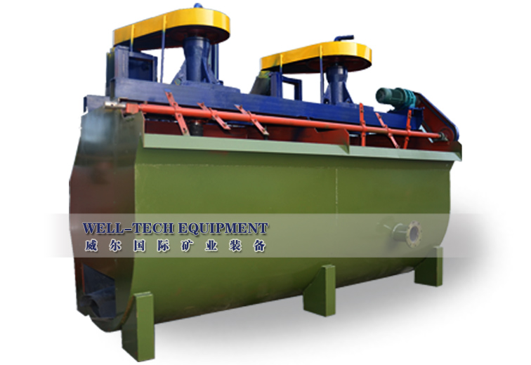
Description
When flotation machine works, slurry is inhaled from the bottom of the cell to the space between impellers. Meanwhile, the low-pressure air send by fan is sent to this area through the air distributor in the hollow shaft. After sufficient mixing, the slurry is pushed out by the impeller, and then goes to the whole cell. When the froth rises to the stable level, after the enrichment processing, froth overflows to the froth trough from the overflow weir. Another part of ore slurry flows to lower part of impeller for the re-mix with air. The remained slurry flows to the next cell until becomes tailing.
XCF and KYF are enforced aeration flotation machine. It has a smaller diameter of impeller, thus lower peripheral speed, saving 30%-50% of power. Because and air distributor is equipped in the tank, air is evenly dispersed. The impeller acts as a centrifugal pump, so as to make the solid particles suspending. The tank is made as U type, reducing sand settlement to the least. Due to reasonable design of the impeller structure and the impeller space,impeller wearing is even, so, the service life of the impeller and stator are extended. Model KYF is unable to spontaneously suck slurry, while has low power consumption. In contrast, model XCF has the ability to automatically suck slurry, and may be allocated horizontally without need for foam pump, but consumes more power than model KYF. Therefore, model XCF and model KYF are combined into a set, i.e., XCF as the sucking tank, and KYF as the direct tank. The combined set can be arranged horizontally without foam pump either.
XCF Cell’s Features:
It has the similar structure and performance with KYF cells and only the difference is the stator on the impeller to be a negative pressure zone. Pulp is sucked automatically but higher power consumption.
Note:
1 Mechanical agitation, no air inhalation but pulp sucked automatically.
2 It is combined with KYF Cells to be group as a suction cell.
KYF Cells’ Features:
1 Impeller is a cone shape with the backward inclined blades, strong agitation and simple structure.
2 Many air distributors are equipped on the impeller cavity, air disperse very well and well mixing of the air and pulp.
3 Utype tank is made and lower sand settlement.
4 The diameter of the impeller is smaller thus lower peripheral speed.
Performance features:
1 Lower power consumption and saving 30-50% energy.
2 Well floated particles and higher recovery.
3 Light wearing of the spare parts so the service life of them are extended.
Note:
1 Mechanical agitation, no air inhalation and no pulp sucked automatically.
2 It is combined with XCF Cells as the direct cells.
Application:
It is widely used in enrichment for non-ferrous metals, black metals and non-metals in medium and big flotation factories for the roughing and scavenging concentration.
Main Technical Parameters of XCF Flotation Machine
|
Model
|
Effective volume(m3)
|
Capacity
(m3/min)
|
Diameter of impeller
(mm)
|
Rotation of impeller
(r.p.m)
|
Pressure of the blower
(Kpa)
|
Maximum air inhalation
(m3/m2.min)
|
Power of agitation motor
(kw)
|
Power of scraper
(kw)
|
Weight
(kg)
|
|
XCF-1
|
1
|
0.2-1
|
400
|
358
|
≥12.6
|
2
|
5.5
|
1.1
|
1154
|
|
XCF-2
|
2
|
0.4-2
|
470
|
331
|
≥14.7
|
7.5
|
1659
|
|
XCF-3
|
3
|
0.6-3
|
540
|
266
|
≥19.8
|
11
|
1.5
|
2259
|
|
XCF-4
|
4
|
1.2-4
|
620
|
215
|
≥19.8
|
15
|
2669
|
|
XCF-8
|
8
|
3.0-8
|
720
|
185
|
≥21.6
|
22
|
3968
|
|
XCF-16
|
16
|
4-16
|
860
|
160
|
≥25.5
|
37
|
6520
|
|
XCF-24
|
24
|
4-24
|
950
|
153
|
≥30.4
|
37
|
8000
|
|
XCF-38
|
38
|
10-38
|
1050
|
136
|
≥34.3
|
55
|
11000
|
Main Technical Parameters of KYF Flotation Machine
|
Model
|
Effective volume(m3)
|
Capacity
(m3/min)
|
Diameter of impeller
(mm)
|
Rotation of impeller
(r.p.m)
|
Pressure of the blower
(Kpa)
|
Maximum air inhalation
(m3/m2.min)
|
Power of agitation motor
(kw)
|
Power of scraper
(kw)
|
Weight
(kg)
|
|
KYF-1
|
1
|
0.2-1
|
340
|
281
|
≥12.6
|
2
|
7
|
1.1
|
826
|
|
KYF-2
|
2
|
0.4-2
|
410
|
247
|
≥14.7
|
5.5
|
1419
|
|
KYF-3
|
3
|
0.6-3
|
480
|
219
|
≥19.8
|
7.5
|
1.5
|
1885
|
|
KYF-4
|
4
|
1.2-4
|
550
|
200
|
≥19.8
|
11
|
2206
|
|
KYF-8
|
8
|
3.0-8
|
630
|
175
|
≥21.6
|
15
|
3600
|
|
KYF-16
|
16
|
4-16
|
740
|
160
|
≥25.5
|
30
|
5900
|
|
KYF-24
|
24
|
4-24
|
800
|
150
|
≥30.4
|
7500
|
|
KYF-38
|
38
|
10-38
|
880
|
139
|
≥34.3
|
45
|
10300
|
Warm reminding:
1. Please inform the product name, model and specification when you order.
2. Please inform the ore feeding direction; otherwise, we make from the left feeding.
3. We won’t offer and install the middling and discharging pipes if customers don’t tell the requirements and offer the flow sheet.
Main Technical Parameters of XCF Flotation Machine
|
Model
|
Effective volume(m3)
|
Capacity
(m3/min)
|
Diameter of impeller
(mm)
|
Rotation of impeller
(r.p.m)
|
Pressure of the blower
(Kpa)
|
Maximum air inhalation
(m3/m2.min)
|
Power of agitation motor
(kw)
|
Power of scraper
(kw)
|
Weight
(kg)
|
|
XCF-1
|
1
|
0.2-1
|
400
|
358
|
≥12.6
|
2
|
5.5
|
1.1
|
1154
|
|
XCF-2
|
2
|
0.4-2
|
470
|
331
|
≥14.7
|
7.5
|
1659
|
|
XCF-3
|
3
|
0.6-3
|
540
|
266
|
≥19.8
|
11
|
1.5
|
2259
|
|
XCF-4
|
4
|
1.2-4
|
620
|
215
|
≥19.8
|
15
|
2669
|
|
XCF-8
|
8
|
3.0-8
|
720
|
185
|
≥21.6
|
22
|
3968
|
|
XCF-16
|
16
|
4-16
|
860
|
160
|
≥25.5
|
37
|
6520
|
|
XCF-24
|
24
|
4-24
|
950
|
153
|
≥30.4
|
37
|
8000
|
|
XCF-38
|
38
|
10-38
|
1050
|
136
|
≥34.3
|
55
|
11000
|
Main Technical Parameters of KYF Flotation Machine
|
Model
|
Effective volume(m3)
|
Capacity
(m3/min)
|
Diameter of impeller
(mm)
|
Rotation of impeller
(r.p.m)
|
Pressure of the blower
(Kpa)
|
Maximum air inhalation
(m3/m2.min)
|
Power of agitation motor
(kw)
|
Power of scraper
(kw)
|
Weight
(kg)
|
|
KYF-1
|
1
|
0.2-1
|
340
|
281
|
≥12.6
|
2
|
7
|
1.1
|
826
|
|
KYF-2
|
2
|
0.4-2
|
410
|
247
|
≥14.7
|
5.5
|
1419
|
|
KYF-3
|
3
|
0.6-3
|
480
|
219
|
≥19.8
|
7.5
|
1.5
|
1885
|
|
KYF-4
|
4
|
1.2-4
|
550
|
200
|
≥19.8
|
11
|
2206
|
|
KYF-8
|
8
|
3.0-8
|
630
|
175
|
≥21.6
|
15
|
3600
|
|
KYF-16
|
16
|
4-16
|
740
|
160
|
≥25.5
|
30
|
5900
|
|
KYF-24
|
24
|
4-24
|
800
|
150
|
≥30.4
|
7500
|
|
KYF-38
|
38
|
10-38
|
880
|
139
|
≥34.3
|
45
|
10300
|
Warm reminding:
1. Please inform the product name, model and specification when you order.
2. Please inform the ore feeding direction; otherwise, we make from the left feeding.
3.
We won’t offer and install the middling and discharging pipes if
customers don’t tell the requirements and offer the flow sheet.

 Well-tech International Mining Equipment Co.,Ltd. is a large benefication service company specialized in designing, manufacturing, installing and debugging of benefication equipment as well as providing flow sheet design and plant design. Our company covers an area of 48,000 square meters, the workshop is 20,000 square meters, we have various large modernized machinery process facilities, professional engineering team and professional installation team.
 Well-tech International Mining Equipment Co.,Ltd. is a large benefication service company specialized in designing, manufacturing, installing and debugging of benefication equipment as well as providing flow sheet design and plant design. Our company covers an area of 48,000 square meters, the workshop is 20,000 square meters, we have various large modernized machinery process facilities, professional engineering team and professional installation team.